MOLDING / PRECISION PLASTICS
Plastic Micro
Injection Molding
Fine holes, thin walls and small functional details. Developed from the material through to inspection.
We combine micro-tool design, material selection, trial molding and dimensional review. The work can start with a new component, a production-intent sample or a difficult feature in an existing design.
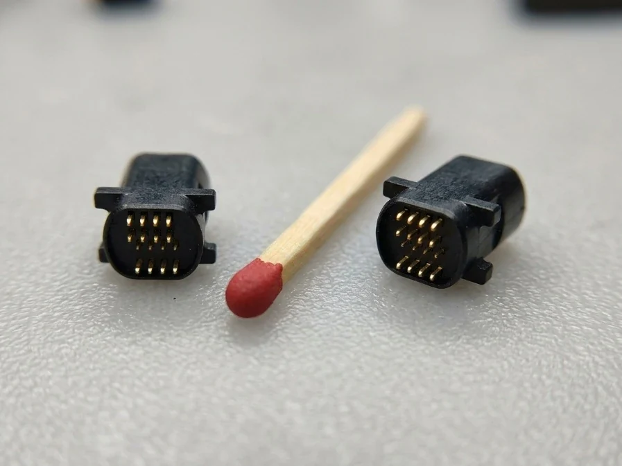
Small parts need a complete manufacturing plan
Project directions include small connector components, precision inserts molded in plastic, fine-feature housings and optical-communication component development. We review filling, part removal, handling, measurement and packing together. An accurate mold is necessary, but the molded part also depends on the resin and process.
Capability and specification review
| Materials | Customer-specified thermoplastics and application-matched grades. Exact resin, filler, conditioning and use conditions are reviewed; polymer family alone is insufficient. |
| Thin-wall reference | Our manufacturing presentation lists 0.04 mm as a selected thin-wall capability, subject to geometry, material, tooling, measurement and production plan. It is not a universal wall-thickness guarantee. |
| Part weight | Minimum finished-part weight is quoted only after review. The presentation’s 0.00024 g entry is labelled a minimum shot-weight direction, not a verified minimum part weight. |
| Critical features | Hole size and pitch, wall section, ribs, mating faces and permitted gate or parting-line marks identified on the drawing. |
| Tolerances | Critical dimensions, datums, measurement method and conditioning state agreed separately from mold-component tolerances. |
| Supply stages | Trial tooling, physical samples, pilot runs and repeat production, with a defined approval point between stages. |
How we develop the part
We review the function and geometry, identify the smallest or least accessible features, and select a tooling route. Material questions and DFM changes are closed before tool release. Trial parts are measured and checked for fit and appearance. Corrections are recorded against drawing revisions. Production preparation includes handling, cavity identification where required, sampling and packing that protects the fine features.
MT ferrules and optical applications
MT ferrules are a dedicated application-development direction. Their hole-array geometry and optical acceptance cannot be inferred from a general machining number. The ferrule page separates the molded geometry, guide-hole interface and later optical assembly tests.
Information that makes a quotation useful
Send drawings with units and revision, resin grade or target properties, critical dimensions, permitted flash and gate marks, quantity for first samples and repeat orders, intended tests and delivery destination. Describe the present problem: short shots, variation, distortion, difficult handling or uncertain material choice. We confirm the proposed process and inspection scope before accepting a delivery plan.
Source basis: NewwaySmart Total Solution presentation, Ultra-Precision Manufacturing Capabilities. Selected references are not universal production specifications.