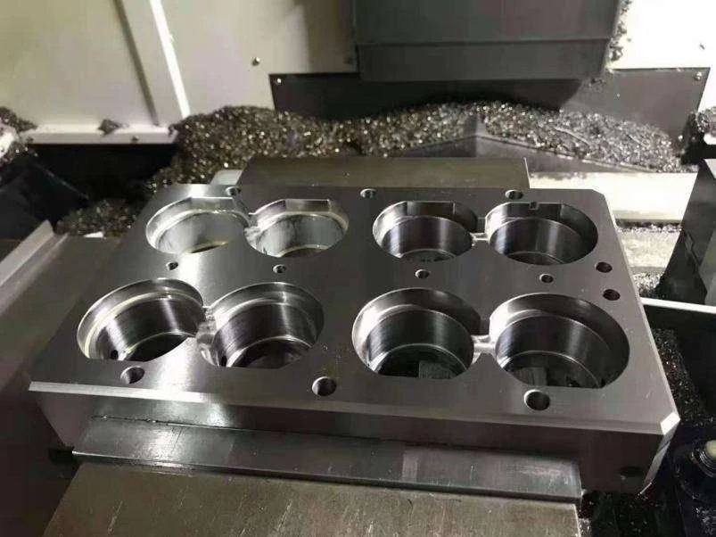
There is no universally best mold lifter. A useful design releases the undercut without damaging the part, carries its intended loads and returns without binding. The lifter head, shank, guide and base connection must be evaluated as one moving assembly—not as independent parts selected from photographs.
What does a lifter do?
A typical angled lifter combines movement along the ejection direction with lateral movement that clears an undercut. This can suit internal features where a conventional external slide is inconvenient. However, an undercut alone does not establish that a lifter is the right solution. The part must remain adequately supported throughout release.
For a simplified straight angled path, with the angle θ measured from the ejection axis, lateral movement is x = H × tan θ, where H is travel along that axis. This is a geometry relationship, not a complete sizing formula. Real mechanisms may include offsets, staged motion or guided couplings; clearances, stiffness, available travel and part retention still need to be checked.
Compare structures by the problem they solve
| Structure to evaluate | Potential reason to choose it | What can invalidate the choice |
|---|---|---|
| Simple angled lifter with sliding base | A direct, maintainable route for a suitable local undercut | Insufficient lateral allowance, long unsupported shank or poor base alignment |
| Guided coupling or self-aligning lifter system | Manage the changing relationship between lifter travel and its supporting base | Incorrect installation envelope, incompatible travel or loading outside the system’s limits |
| Replaceable head and supported shank arrangement | Service a wear-prone forming feature without replacing every element | Weak connection, difficult access or inadequate support of the head |
| Slide, collapsible core or staged mechanism instead | An undercut requiring a different release path or sequence | Added complexity without a clear benefit, inadequate space or unavailable machine control |
DME’s UniLifter illustrates a coupling moving within a T-gib to address binding associated with some fixed-angle arrangements. DME also offers other lifter systems. These are examples of different approaches to motion control, not a claim that one brand or structure is superior for every mold.
A larger angle is not a free increase in performance
Increasing the angle changes lateral travel for a given ejector movement, but also changes the geometry of support, contact and available installation space. Before choosing an angle, check head clearance, shank section, unsupported length, contact loading and the relationship with neighboring ejectors. Do not copy an angle from another mold simply because its component looks similar.
The forming surface must release the intended material without an unacceptable scrape, drag mark or deformation. Review draft and surface direction at the lifter feature together with the local shrinkage and the order in which the part releases from other tooling surfaces.
Return position deserves the same attention as ejection
A mechanism can eject correctly once and still be unreliable when returning. Verify the support and clearances throughout both directions of travel. Define how the lifter reaches its molding position and how closing is prevented until the necessary elements have returned. Do not rely on a vague instruction to check before closing where the machine or mold needs a positive interlock.
Trial acceptance should cover repeated movement, part condition, fitting at the shut-off, wear indicators, thermal behavior and maintenance access. Specify which observations require adjustment or replacement rather than accepting a successful single hand-cycle as production proof.
Ordering lifters and related precision components
NewwaySmart provides drawing-based lifters and ejection components, forming inserts and associated precision machining. The supply scope can be an individual component, matched parts or engineering and fitting within a complete tool. It must be stated explicitly in the quotation.
Send the undercut section, part material, desired release direction, available ejector stroke, mold layout, guide and base interfaces, steel and hardness, quantity and inspection requirements. For a failure investigation, add wear photographs and a description of when binding occurs. Review related slide options before committing to a mechanism.
References
DME UniLifter system overview; DME Accualign lifter systems. Final design requires a project-specific motion, strength, fit and safety review. Discuss a lifter requirement.