A precision claim is useful only when the controlled feature and verification method are clear. Nominal size, location, surface and final product performance are different requirements.
Four numbers that must not be confused
Nominal diameter: 0.6895 mm describes a pin’s intended size, not its permissible variation. Dimensional tolerance: upper and lower limits define accepted size. Position tolerance: a feature-control frame locates a feature relative to specified datums and other applicable drawing rules. Measurement uncertainty: expresses the uncertainty associated with the measurement result, not a manufacturing tolerance.
Unit conversion also matters: 0.1 µm equals 0.0001 mm or 100 nm. A drawing callout of 0.0007 mm is 0.7 µm, not 0.1 µm. Where a diameter symbol defines a positional tolerance zone, do not rewrite it as a plus/minus coordinate tolerance without an engineering interpretation of the complete drawing.
What selected precision means at NewwaySmart
NewwaySmart identifies selected MT-related positional requirements at the 0.1 µm level within its specialist capability. Each quotation must identify whether that requirement applies to a tooling component, a hole array, a molded ferrule or a measurement result. The drawing revision, datum system, feature length, material condition and acceptance method are reviewed before commitment.
This capability does not mean that every surface of a conventional mold requires or receives a 0.1 µm tolerance. It also does not convert one qualified feature into a universal statement about every tool size, material or production process. Our role is to apply specialist precision where the product needs it and conventional controlled manufacture where that is the correct solution.
A measurement plan before manufacture
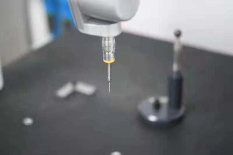
Agree the datum establishment, fixture, measurement method, locations and reporting format. For demanding features, consider temperature, cleanliness, part conditioning, repeatability and measurement uncertainty together. Instrument display resolution alone does not demonstrate the ability to accept a feature tolerance.
For optical ferrules, separate geometric inspection from assembled optical validation. Fiber-hole geometry, guide-hole relationships and alignment pins contribute to the connection. A visually clear microscope image does not establish insertion loss, and a nominal guide-pin diameter does not specify hole-array location.
Use the correct standard and edition
ISO’s current published plastic-part tolerance reference is ISO 20457:2026, published in August 2026. The Chinese official portal lists GB/T 47067-2026, Plastics moulded parts—Tolerances and acceptance conditions, as current, effective 1 August 2026. Cite the actual agreed edition in the purchase documents; do not silently replace the contractual basis or assume that similarly titled editions are identical.
Metal tool-component inspection and plastic molded-part acceptance are not interchangeable. Resin behavior, process conditions and conditioning can affect the finished part even when the tool component meets its drawing. An approved part specification therefore needs its own verification, rather than a blanket copy of the mold machining tolerance.
Precision pins and sleeves · MT tooling · Review a critical feature ↗
Capability values: NewwaySmart’s October 2026 project information. External references: ISO 20457:2026; GB/T 47067-2026 official record; US Conec MT alignment explanation. This article does not replace a dimensional inspection report.