MOLD COMPONENTS / FORMING PINS
Precision Forming Pins
& Micro Core Pins
Small working features. Controlled shoulders, fits and finished dimensions.
We supply drawing-based forming pins independently or within a complete tool. The scope includes the working tip, locating and retaining features, finishing, inspection and protected packing. A pin that forms a bore is specified differently from a guide pin that aligns a tool or an ejector pin that removes a part.
What we can supply
Straight and stepped forming pins, shoulder-located pins, replaceable micro core pins and drawing-specific tip profiles. Applications include fine holes, connector features and precision molding interfaces. The tool design determines support length, retention, anti-rotation features and replacement access.
Specify the whole pin, not only its diameter
| Feature | Information to define |
|---|---|
| Working diameter | Nominal size, upper and lower limits, measurement length and final surface condition. |
| Step and shoulder | Step lengths, locating face, permitted corner radius, relief and axial seating. |
| Geometric control | Straightness, roundness, cylindricity, runout or axis position, as required by the drawing; these are separate characteristics. |
| Material and treatment | Specified grade, final hardness, heat-treatment route, corrosion or wear requirements and traceability. |
| Surface | Working-zone roughness, lay direction where relevant, polished length, coating specification and masked interfaces. |
| Inspection | Datum establishment, instrument and method, temperature, sampling, measurement uncertainty and acceptance decision. |
| Delivery | Quantity by drawing revision, matched-set identification, spare count and protection of the working tips. |
A 0.6895 mm pin is a size, not a tolerance
Nominal 0.6895 mm precision pins are one example of the component requirements we can discuss. The size limits, roundness, working length, finish and mating fit must still be written into the specification. Likewise, a positional requirement for an array or an assembled tool is not established by measuring the pin diameter alone.
For demanding MT-related work, the pin, locating insert, tool assembly and molded part are reviewed as connected but separately inspected items. Selected sub-micron features are supported through a drawing-specific manufacturing and measurement plan, rather than applying one universal tolerance to the entire mold.
Manufacturing and acceptance
We agree the supplied and finished conditions before machining. Precision grinding, profile machining, EDM or other suitable operations are chosen around the material and geometry; heat treatment and any coating are included in the dimensional plan. Final inspection refers to the delivered condition, with the working area protected during handling and shipment.
A drawing review identifies fragile unsupported lengths, finishing access and features requiring a separate process trial. Repeat batches retain the agreed revision and inspection basis. A changed mating component, material or treatment is reviewed before it is accepted as an interchangeable replacement.
Send a pin inquiry
Provide the 2D drawing and revision, available 3D data, material and hardness, quantity, key dimensions, finish, mating interfaces, required report and arrival date. For replacements, identify the original tool and which dimensions describe the intended design rather than wear on the old pin.
Request a forming-pin review ↗ · Read the metrology guide · MT tooling
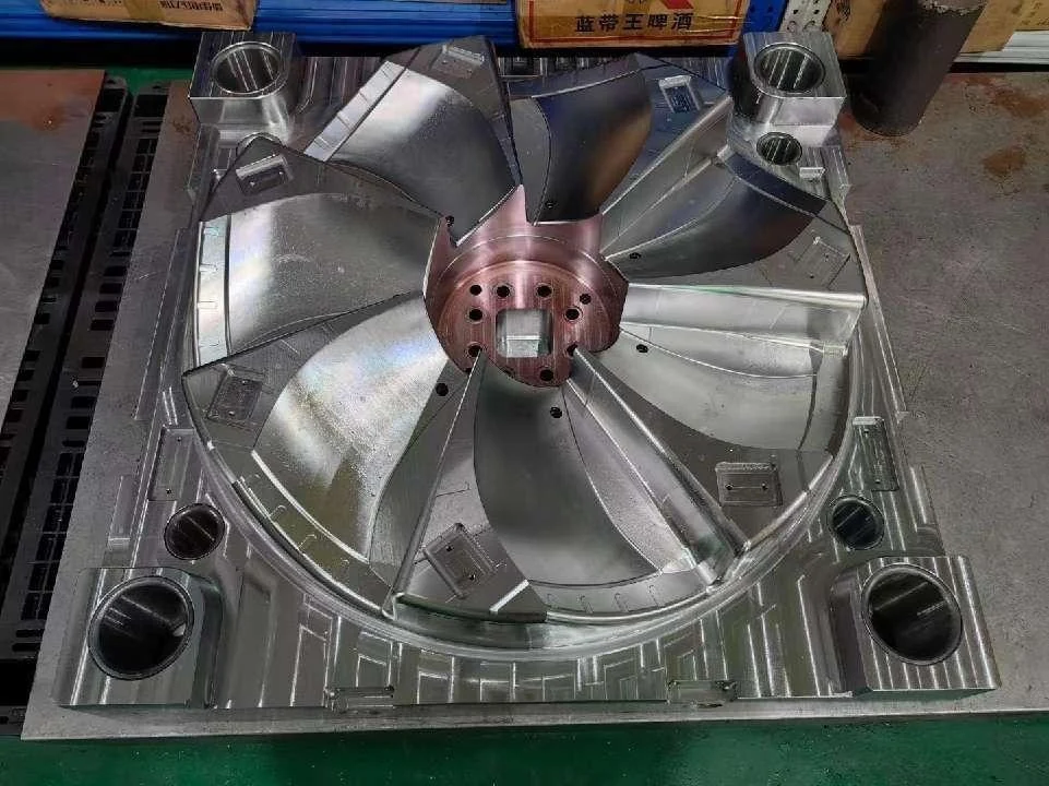
The current photograph is a tooling-machining reference, not a dimensional inspection of a specified pin. Reference nomenclature: MISUMI mold components. Component supply is defined by the approved drawing and inspection scope.